Note: this essay was written by the National Weather Service Forecast Office in Burlington, Vermont and tipped to me by a reader. Vermont's wind farm acreage pales in comparison to places like the Texas and Oklahoma, where there are literally thousands of acres of wind farms right in the middle of tornado alley. I've been there and seen them firsthand.
Certified Consulting Meteorologist Mike Smith writes:One has to wonder just how much trouble wind farms are causing the nation's doppler radar warning system. It looks like a classic case of the law of unintended consequences at work. - Anthony
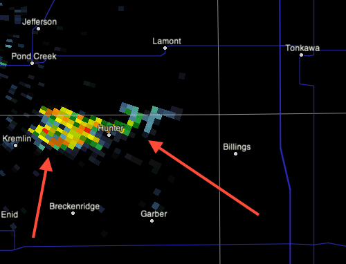
"While driving to Norman, OK recently I saw the newest "wind farm" to the west of Interstate 35 southwest of Tonkawa. Wind farms show up as bright ground clutter on weather radars and here it is."
National Weather Service WSR-88D Radar and Wind Farm Impacts
Introduction
The most valuable tool used by the National Weather Service (NWS) to detect precipitation is the radar. Radar stands for Radio, Detection, and Ranging, and has been used to detect precipitation since the 1940′s, with most of the technology coming from the military.
The radar used by the NWS is called the WSR-88D, which stands for Weather Surveillance Radar-1988 Doppler (1988 is when the radar was first built). The WSR-88D is a Doppler Radar, which indicates the radar detects motion toward or away from the radar as well as the location and intensity of precipitation. The ability to detect motion along with numerous other radar enhancements over the years, have enabled NWS meteorologists to examine storms with more accuracy and determine if there is rotation or hail within the area of precipitation associated with a thunderstorm. In addition, radar algorithms have helped NWS meteorologists determine strength and depth of rotation, along with intensity and type of precipitation for warning decisions.
There are 155 WSR-88D Doppler radars in the United States, including the U.S. Territory of Guam and the Commonwealth of Puerto Rico. Most radars are operated by the NWS or the Department of Defense. Click here to view a map of the WSR-88D Doppler Radar network. Figure 1 shows the network of radars across the United States, Guam, and Puerto Rico. The NWS office at Burlington (BTV), VT has control of two radars. The first radar is located in Colchester, VT (KCXX) and is owned and operated by the NWS. The second radar is located in Montague, NY (KTYX) and is maintained and owned by the Department of Defense (DOD). Forecasters at the Weather Forecast Office (WFO) in Burlington also use surrounding radars from Albany NY, Binghamton NY, Buffalo NY, Gray ME, and Boston MA for decisions concerning watches, warnings, and advisories.
Figure 2 shows a close up of radar sites across the Northeast United States. Each radar site is strategically placed to cover a particular part of the region, with only limited gaps in the areal coverage area usual caused by mountains.
The following products are available from each radar site: composite reflectivity, base reflectivity, velocity, storm relative motion, precipitation estimates, and numerous algorithms to enhance storm interrogation. For additional information on the NWS radar and the associated products, click here.
In this article, we will discuss how the Doppler radar works and influences of wind farms on both KTYX and KCXX radar data. We will show examples of several radar products impacted by wind farms. In future articles, we will examine severe weather radar signatures and how NWS meteorologists use them, winter weather precipitation returns, beam blockage issues from the Green and Adirondack Mountains, and other non-meteorological artifacts detected by the NWS Doppler radar.
Doppler Radar Theory
The WSR-88D radar obtains weather information (precipitation and wind) based upon returned energy. The radar emits a burst of energy, when the energy strikes an object (raindrops, snowflakes, bugs, birds, mountains etc), the energy is scattered in all directions. A small fraction of the scattered energy is directed back toward the radar. The radar receives this reflected signal during its listening period, and then computers analyze the strength of the returned pulse, time it took to travel to the object and back, and phase shift of the pulse. This process of emitting a signal, listening for any returned signal, then emitting the next signal, takes place very fast, up to 1300 times each second. The better the target is at reflecting radio waves (i.e. more raindrops, large hailstones, ice, etc), the stronger the returned energy or echo will be.
The WSR-88D pulses have an average transmitted power of 450,000 watts. By comparison, a home microwave has about 1000 watts of energy. Figure 3 shows the radar transmitting a pulse in green toward an object in blue. As the pulse intersects the object return energy is sent back toward the radar, and the intensity and distance can be determine from this energy. Click here for an animation of this principle.
Doppler radar systems can provide information on movement of targets and their position. The Doppler principle for radar is similar to that observed with sound waves. An object emitting sound waves will transmit those waves in a higher frequency when it is approaching your location (inbound velocity) and as the object moves away from your location, the sound waves will be stretched and have a lower frequency (outbound velocity). This is the phenomena responsible for the change in pitch of a train whistle as the train or moves past you.
The echo intensity (reflectivity or Z) is measured in dBZ (decibels of Z) during each volume scan. The dBZ values increases as the strength of the signal returned to the radar increases and usual the dBZ values range from 5 to 75. Light rain or snow typically has a dBZ return between 20 and 30, while severe thunderstorms can have dBZ values, which reach 65 to 75. Typically the higher the dBZ value, the higher the rainfall or snowfall rate.
The WSR-88D employs scanning strategies in which the antenna automatically raises to higher and higher preset angles or elevation slices, as it rotates. These elevation slices comprise a volume coverage pattern (VCP). The two main operating VCPs used by forecasters are clear air mode and precipitation mode. These different VCPs have varying numbers of elevation tilts and rotation speed, which help to analyze and provide different perspectives of the atmosphere. Click here to learn more about different VCP's and the associated elevation slices.
Forecasters at WFO BTV use VCP 212 for severe weather operations, because it provides the best low-level vertical scan of the atmosphere in the shortest amount of time (less than 5 minutes). We use VCP 121 for light to moderate widespread rain or snow and VCP 31 or 32 for clear air operations, when no or very light precipitation is falling.
Click here for a VCP quick reference comparison chart used by forecasters at WFO BTV. Josh Korotky (Science and Operation Officer at WFO State College) developed this chart. The right part of the chart shows the different elevation slices with each volume scan, while the middle part of the chart indicates the VCP and the time it takes the volume scan to be complete, along with maximum range R (reflectivity) and V (velocity) data can be observed. Finally, the remarks section on the left side provides user with a brief description along with strengths/weaknesses of each VCP.
Wind Farm Impacts on Doppler Radar
In this section, we will discuss the impacts that numerous wind energy generating turbines or wind farms have on radar sampling and the potential for erroneous data. Wind farms impact radars in several ways, especially whenever the wind turbine blades are in motion and located within the radar's line of sight. The turbines can block a significant percentage of the radar beam and decrease the radar signal power down range of the wind farm, particularly if the wind farm is within a few miles of the radar. The wind farm can reflect energy back to the radar system and this appears as clutter or false reflectivity data. This contaminated data can create false precipitation estimates and disrupt precipitation algorithms used by the radar and other software programs.
Wind farms located within 30 nm or within sight of the radar, can significantly impact velocity and spectrum width data, which can cause bad data sampling of rotating storms and false storm motions, along with impacting algorithms used by the radar to process this data. Schemes designed to filter out the ground clutter do not work properly.
Other impacts include, multi-trip/multi-path returns, which creates a false signal down the radial from the wind farm reflectivity region. This can cause confusion and distraction to forecasters, especially during widespread convective or thunderstorm events.
Both KTYX and KCXX have wind farms located within 30 nautical miles (nm) of the radar, which affects data sampling. For KTYX, the Lowville Wind Farm near Lowville, NY on the Tug Hill Plateau is located 2 to 10 nm from the radar, covering from north (010 degrees) to southeast (120 degrees) with over 100 total wind turbines. Additional proposed wind farms to the west of the radar, and to the southeast of the radar, would further influence radar sampling and data quality. Meanwhile, the wind farm near Altona, NY is located in northern Clinton County, NY and is between 25 and 35 nm northwest of the KCXX radar in Colchester, VT.
Wind farms affect both radars in several ways; first, the turbines can block a significant percentage of the radar beam and decrease the radar signal power down range of the wind farm, particularly if the wind farm is within a few miles of the radar. Second, the wind farm can reflect energy back to the radar system and this appears as clutter or false reflectivity data. This reflectivity can create false precipitation estimates and disrupt precipitation algorithms used by the radar and other software programs. Finally, wind farms can significantly influence velocity and spectrum width data, which can cause bad data sampling of rotating storms and false storm motions, along with impacting algorithms used by the radar to process this data. Since the wind turbines have motion and produce reflectivity, schemes designed to filter out the clutter do not work properly.
Given the Lowville Wind Farm near Lowville, NY is within 5 nm of the KTYX radar, several other impacts have been observed, which affect radar sampling. They include, multi-trip/multi-path returns, which creates a false signal down the radial from the wind farm reflectivity region. This can cause confusion and distraction to forecasters, especially during widespread convective precipitation events. For addition information on impacts of wind farms on NWS radar, click here.
Examples of KCXX radar products impacted by Wind Farms
In this section, we will show the locations of the wind farms in relation to the radar sites, samples of wind farm effects on velocity (V), reflectivity (Z), and radar estimated precipitation products. We will show an example of a thunderstorm that developed very close to the wind farm in Clinton County, New York.
Figure 4 shows the KCXX radar location, along with the composite reflectivity in clear air mode, and the associated ground clutter caused by the wind farm near Altona, NY, which is located northwest of the radar. The small blue crosses indicate the location of the two wind farms in Clinton County, New York, while other returns in the composite reflectivity is associated with areas of ground clutter caused by buildings, hills, mountains, and other non-meteorological targets.
Figure 4 also shows the KCXX radar is located between 25 and 30 nm miles from the Altona Wind Farm (blue crosses) and results in the white colored dBZ returns, which indicates ground clutter caused by the wind farm. The wind farm impacts the 0.5° and 0.9° radar elevation slices, because the turbines are located on the eastern slopes of the Adirondack Mountains at an elevation of 1350 feet. However, the wind farm near Chateaugay, NY in northwest Clinton County, NY is located greater than 35 nm from the KCXX radar and no ground clutter is created, because the lowest radar elevation scan is above the height of the wind turbines.
Note the red and purple returns near (between 5 and 10 nm) the KCXX radar associated with ground clutter, such as buildings and the clutter associated with the Green Mountains to the east and the Adirondack Mountains to the west across northern New York. These mountains create ground clutter and contaminate our data, but also block the beam and create poor data sampling, especially in the lowest elevations scans.
Figure 5 shows the impact the Altona, NY Wind Farm has on the lowest four elevation scans (0.5°, 0.9°, 1.3° and 1.9°) from the KCXX radar in Colchester, VT.
Note the ground clutter in the first two elevation scans (0.5°, 0.9°), indicated by the red dBZ returns (circled in yellow), but the higher scans (bottom two displays) show no clutter, because the height of the radar beam is higher than the wind farm.
Figure 6 shows the KCXX storm total precipitation (STP) display across the Champlain Valley and extreme northwest NY. Note the purple to white pixels (circled yellow in figure 6 above) which indicates precipitation estimates of 10 to 15 inches. This over-estimate in storm total precipitation is caused by the radar detecting motion and reflectivity produced by the wind farm.
Forecasters at WFO BTV have since developed precipitation exclusion zones, which prevent accumulating precipitation from occurring near the wind farms and over the mountains, where clutter is usually detected.
Figure 7 shows the KCXX 0.5° base reflectivity and the associated ground clutter caused by the Altona, NY Wind Farm. Note the red dBZ returns of 50 to 55, which would suggest heavy precipitation if the returns were real.
The white crosses in the image indicate the location of the wind turbines, 25 to 30 nm from the KCXX radar. The wind farm produces reflects energy from the radar system that appears as clutter, and contaminates the reflectivity data.
Another product from the KCXX radar impacted by the Altona, NY wind farm is the 0.5° base velocity. Remember, Doppler radar can measure winds moving toward the radar (green color) and away from the radar (red color). This helps forecasters determine winds associated with precipitation, strength/depth, and movement of a storm.
Figure 8 shows the 0.5° base velocity from the KCXX radar. Once again, you can see erroneous velocity data caused by the wind farm located between 25 and 30 nm from the radar. The yellow circled area on figure 8 shows velocity wind measurements of up to 80 knots (redish white color), caused by the movement of the wind turbine blades. This bad data sampling can cause tornado vortex and meso-cyclone algorithms to detect false circulations and alert forecasts, which can be distracting during the warning decision making process.
The next example shows a thunderstorms developing near Altona Wind Farm. Weather patterns show winds from the Champlain and Saint Lawrence River Valleys converge across the northern Adirondack Mountains. This converging of moist/unstable air rises due to the slope of the terrain causing thunderstorms to develop and given the location of the wind farm, these storms can be difficult to detect, especially in the early developmental stages.
Figure 9 (click here) shows a looping 0.5° base reflectivity from the KCXX radar. This loop shows the Altona Wind Farm located just south of Altona NY, which is displayed on the image by the higher (yellow/red color) dBZ returns. As the image loops, note the bright yellow and red dBZ returns that occur near the wind farm, and then moves northeast toward the Champlain Valley. This figure shows a clutter of showers and thunderstorms that developed on 26 June 2009 at 1651 UTC in the vicinity of the wind farm. Note this cluster of showers continued to intensify as they encountered the Champlain Valley. Forecasters at WFO BTV have witness this type of activity several times during 2009 convective season.
Figure 10 shows a frame-by-frame 0.5 base reflectivity of a developing shower over the Altona Wind Farm. The first image (left) at 1651 UTC on 26 June 2009 shows no shower, just the wind farm. Meanwhile, at 1656 UTC and 1701 UTC you can see the development of the shower over the wind farm, then moving toward the Champlain Valley by 1706 UTC and intensifying.
Note the strongest dBZ returns are stationary just south of Altona, associated with the Doppler radar detecting the wind farm in the lowest elevation scan.
Examples of KTYX radar products impacted by Wind Farms
In this section, we will show examples of KTYX radar data being impacted by the Lowville Wind Farm, which is located 2 to 10 nm from the radar. The KTYX radar is located on the Tug Hill Plateau east of Lake Ontario near the town of Montague, NY. The Lowville Wind Farm consists of over 100 turbines, which extent from north (010°) to southeast (120°) of the KTYX radar. The greater the number of wind turbines within a few miles of the radar, increases the amount of beam blockage and attenuate the radar signal down range of the wind farm. In addition, more clutter is created, along with higher precipitation estimates, from the greater number of wind turbines.
Figure 11 shows the KTYX composite reflectivity and associated ground clutter created by the Lowville Wind Farm. In the image, you can see the strong dBZ returns of 60 to 70, which suggest very high-energy returns, created by the wind turbines.
The closeness of this particular wind farm to the radar site significantly blocks radar data and produces very poor sampling across the western Adirondack Mountains and parts of southern Saint Lawrence County in northern New York. We will show examples of the Lowville Wind Farm impacting reflectivity and velocity data, along with some radar algorithms being affected.
Figure 12 shows the Lowville Wind Farm from the KTYX radar tower, looking toward the northeast. It is interesting to see how high the wind turbine blades extend above the tree line. The wind turbines are between 300 and 400 feet above the ground.
Figure 13 (below) shows the KTYX 0.5° base reflectivity and the location of the Lowville Wind turbines and the associated ground clutter they produce. The wind turbines are labeled in white crosses in the figure and the associated ground clutter caused by the wind turbines is outlined in white.
The KTYX radar location is labeled in yellow and the 1 nm, 3 nm, and 10 nm range rings are in yellow.
Figure 14 shows the KTYX 0.5° base reflectivity (left), velocity (right) data, and the mesocyclone detection algorithm in yellow. The white circled areas on the images shows ground clutter from the Lowville wind farm. The velocity figure on the right shows contaminated velocity data due to the rotating turbine blades located down range of the wind farm.
The chaotic wind velocities associated with the rotating turbine blades triggers the KTYX radar mesocyclone detection algorithm (yellow circles) to alert forecasters of potential rotation. These yellow circles indicate an inbound/outbound wind couplet. However, because no precipitation is detected and only a small and nearly stationary velocity couplet is displayed near the wind turbines, meteorologists can determine these low-level circulations are not real.
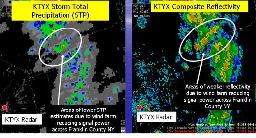
Figure 15 shows the KTYX storm total precipitation (left) and radar composite reflectivity (right). Note the significantly reduced storm total precipitation highlighted by the white circle 15 to 20 nm from the radar. In addition, the image on the right shows significantly weaker reflectivity returns due to The Lowville Wind Farm blocking the beam and reducing the signal power of the radar to detect precipitation.
The two images show lines of poor radar data sampling (white arrows), due to the angle at which the radar signal intersects the wind turbines. Meteorologists use surrounding WFO radars, surface observations, and interpolation techniques to estimate the reflectivity and precipitation, which is reduced by the wind farm.
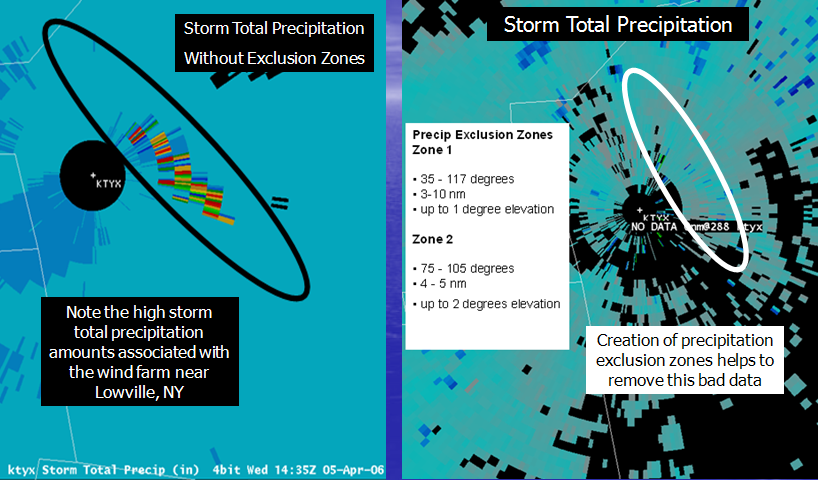
Figure 16 shows the KTYX storm total precipitation product before the development of precipitation exclusion zones (lower left) and then storm total precipitation after the creation of exclusion zones (lower right). Note the high storm total precipitation amounts of 6 to 9 inches associated with the contaminated data from the wind farm.
This bad data is excluded from the storm total precipitation product by the use of precipitation exclusion zones and results in a much better representation of actual rainfall estimates. This contaminated data, if not corrected, can be ingested into river forecasting models and can cause erroneously high forecast river levels.
Meteorologists at WFO BTV have noticed on numerous occasions the Lowville Wind Farm has produced very poor data, influencing areas far from the radar across southern Saint Lawrence County and western Adirondack Mountains in northern New York. Figure 17 shows the KTYX base velocity with spurious multi path scattering caused by the wind farm turbines. The green and red single lined pixels extending down the radial are caused by multi-path and inter-turbine scattering of the radar beam. The white arrows identify areas where multi-path scattering is occurring. This scenario causes significant reduction in data quality many miles from the radar and wind turbines. In addition, this poor data quality can lead to false low-level circulations or false areas of light precipitation. In some strong wind conditions, when environmental conditions are just right, false tornado vortex signatures (TVS) will be detected by the radar. In these cases, we try to invoke more suppression to reduce the clutter and impacts caused by the wind turbines.
As the demand for energy continues to increase, the development of clean efficient wind energy produced by wind farms will continue to grow. The development of wind farms within the line of sight of radars will continue to increase, resulting in the continued reduction in data quality. Meteorologists have noticed impacts to reflectivity, velocity, storm relative motion, and precipitation estimate data with radar located within 30 nm of a wind farm. WFO BTV continues to monitor wind farm development across the North Country and the potential impacts to our radar quality.
WFO BTV continues to adapt our radar data interpretation techniques and training to provide the public with the best possible watches, warnings, and advisories products for the protection of life and property. Finally, we continue to update our clutter suppression methods and precipitation exclusion zones to provide our users with the best radar data quality possible.
References
Information on radar and how Doppler Radar works.
Information on Doppler Radar and Associated Impacts Caused by Wind Farms



Reader Comments
to our Newsletter